Blast-Resistant Engineering
We define the blast loads a building must resist and design its structure, envelope and openings to the agreed level of protection. Analysis runs on PNH's own single-degree-of-freedom engineering tool and is issued under the review of PNH's Chief Technical Officer.
What PNH Does
Blast load definition
Airburst, close-in and confined detonations; contact effects by breach and spall methods.
Structural response
Reinforced concrete, steel and masonry elements checked by single-degree-of-freedom and pressure-impulse methods.
Envelope and facades
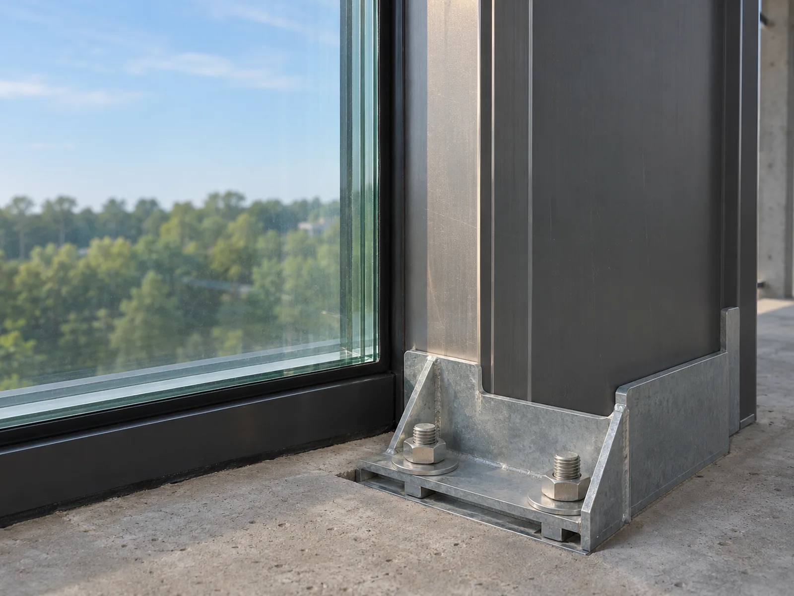
Walls, roofs, curtain walls, glazing, doors and louvers designed or specified to the level of protection.
Disproportionate collapse
Alternate load path and key element checks to ASCE/SEI 76-23.
Tender support
Element sizes, reinforcement, interface loads and budgetary quantities a contractor can price from.
Vendor items
Performance specifications for blast-rated doors, windows and louvers, and review of vendor data sheets.
Independent and Engineer-Led
PNH does not make, sell or install protective products. Analysis is performed in house with PNH's own tools and issued under the review of PNH's Chief Technical Officer. Every assumption is documented and traceable to the governing criteria.
Related Services

Threat, Vulnerability and Risk Assessment
What could happen at a site, how likely it is and how bad it would be, with measures ranked by risk reduced per dollar.
Learn more →
Hostile Vehicle Mitigation
Every credible approach route, the speed a vehicle can reach at each barrier line, and the tested rating that stops it.
Learn more →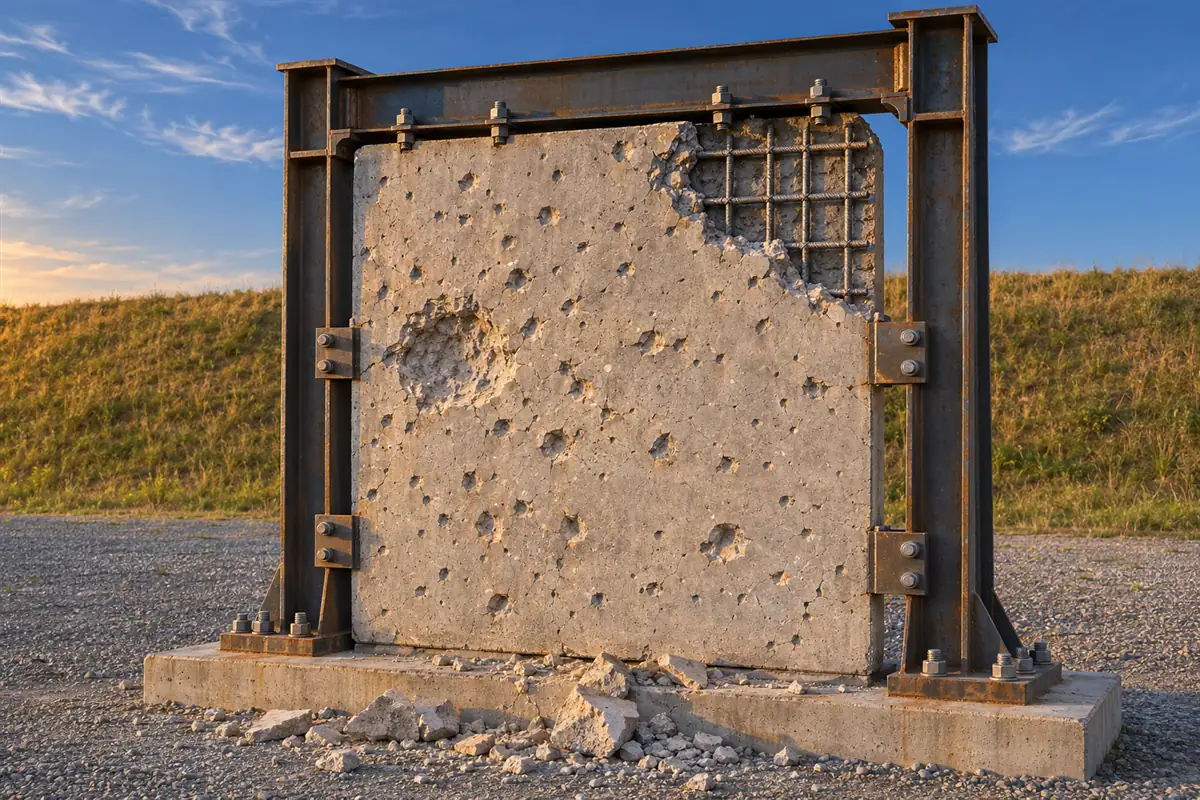
Blast, Fragment and Impact Analysis
What strikes a structure besides the pressure wave: fragments, debris, direct impact and secondary fire.
Learn more →Blast-Resistant Engineering: Common Questions
Do you provide pre-bid blast design for tenders?
Yes. PNH prepares load assessments, preliminary designs, element schedules, interface loads and budgetary quantities that contractors price their tenders from, on the tender schedule.
Do you prepare CAD or shop drawings?
PNH provides design sketches and detail visualizations. Fabricators prepare CAD and shop drawings because they need accurate field measurements.
Do you use finite element analysis?
Most blast design work is done with validated single-degree-of-freedom and pressure-impulse methods. Where a project truly needs nonlinear finite element analysis, PNH scopes and prices it separately with the client's approval.
Discuss Your Blast-Resistant Engineering Project
Send us the site and the deadline. A short note on the site, what concerns you and when the tender or decision is due is enough to start. We reply within one business day.
- The siteAn address, a site plan or a few photos.
- The concernThe threat question, an incident or a client requirement.
- The criteriaAny standard or client specification that applies.
- The dateWhen the tender, review or decision is due.
Email pnhsec@pnhsec.com or call +1-818-253-9557